The goal of this session is to become acquainted with the basic input and output features of the ESP32 with MicroPython.
We have an ESP32 board and a breadboard with two push buttons and an LED. Firstly, let's try to switch the LED on when we press the left button, and to switch it off when we press the right button. Here is the wiring (which may vary depending on the development board you use), for an ESP32 DevKit V4 board by Espressif:
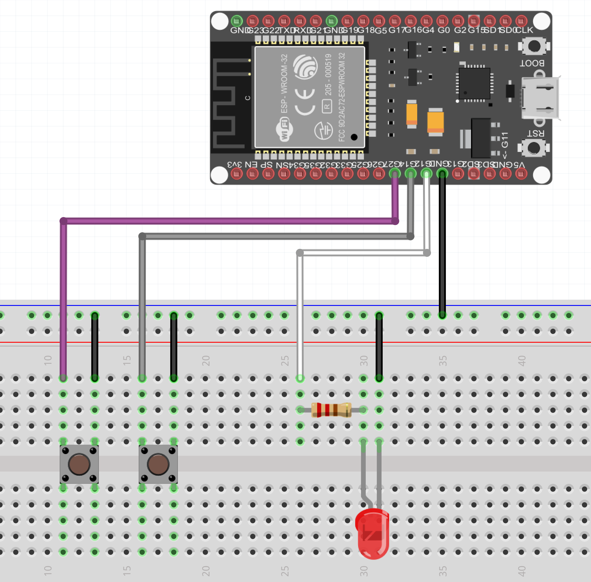
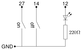
which corresponds to the following electrical circuit:
Take care of the polarity of the LED. The current must flow through the LED from the anode (long leg, small electrode inside the bulb) to the cathode (short leg, big electrode inside the bulb) to the ground. You can connect the resistor to either leg, but the output pin must feed the LED through the anode, and the cathode must be on the ground side.
The name of the pins on your card may vary: GPIO27 or D27 instead of just 27. Consult the reference manual of your development board to find which pin is connected to which GPIO. MicroPython on the ESP32 uses the GPIO number of the pin as pin identifier.
The value of the resistor is not critical. With an output voltage of 3.3V and a voltage across the LED of 1.7V, we get a voltage of 1.6V across the resistor. A 220Ω resistor will setup a 7.3mA current in the LED, which is enough to light it and will limit the current to 15mA if it is accidentally connected to a 5V source.
Programming
In your Python program, you will have to refer to the logic level imposed by the push buttons on pins 27 and 14, and you will have to set the logic level on pin 12 to switch the LED on or off. For this, you need to access these pins using the Pin class of the machine module:
machine.Pin(num)- create an object that represents GPIO pin number
num. For instance, in our setup, theonbutton is plugged on GPIO pin number 27, so we should write:on = machine.Pin(27) pin.init(mode=mode, pull=pull)- initialize the pin with the provided parameters.
modecan bemachine.Pin.INfor an input pin, ormachine.pin.OUTfor an output pin. It can also bemachine.Pin.OPEN_DRAINfor an open drain output pin (no output voltage is imposed excepted 0 when the pin is low).
pull@ can be either None to let the pin float freely, machine.Pin.PULL_UP to pull the pin to the high logic level with an internal resistor, or machine.Pin.PULL_DOWN@@ to pull the pin towards the low logic level with an internal resistor.
pin.on()- set the pin to the high logic level
pin.off()- set the pin to the low logic level
pin.value()- get the current logic level of the pin (the result is undefined for an output pin)
pin.value(val)- set the logic level of the pin to val. If the pin is an input pin, this level is memorized and will be set when the pin becomes an output pin.
For this exercise, the following code may be used to setup the pins:
Pins 27 and 14 are configured with a pull up resistor so that they are high when the push button does not force them to zero.
Switch the LED on or off by polling
Firstly, we will switch the LED on when the on button is pressed and switch it off when the off button is pressed. We will detect pressed buttons by periodically reading the value of the corresponding pin. Remember that when a button is pressed, it connects the corresponding pin to the ground, so the value of the pin will be zero. Try it by yourself before looking at the solution.
Switch the LED on or off using interrupts
We will now use interrupts to switch the LED on and off when the buttons are pressed. To register an interrupt handler on a pin when the signal goes from high to low, you can use the following code:
Make the LED blink using delays
To make the LED blink at 1Hz, we can just switch it on, wait for 500ms, switch it off, wait for 500ms and start again:
Make the LED blink using a timer
It is much more efficient to use a timer to decide when the LED should change its state. The timer is a hardware device that counts ticks on a clock and triggers an interrupt when the count is over. This does not consume CPU time.
Combining buttons and blinking
We now want the right button to make the LED blink and the left button to set the LED on. Since we cannot create a timer in an interrupt handler, we have to create it before hand and to activate or deactivate it when needed:
The ultimate exercise: handle bouncing buttons
We now want to switch between three modes: the LED is off, the LED is on, the LED is blinking. However, we have only two buttons. We will use the right button to switch the lED off, and the left button to switch it on. The blinking mode will be activated when we ''double clic' the left button. However, most push buttons bounce: when you push and release them, the mechanical parts oscillate and they produce several rising and falling edges. Therefore, we should eliminate events that are too close (less than 200ms is OK with most cheap push buttons). Then, we will consider that when two press events are separated by less that 500ms, it is a double click, otherwise, it is a simple click.
Look at the documentation of the time (or utime) module to find the relevant functions. Try to write the code, then, and only then, look at the proposed solution.