CentraleSupélec LMF, UMR CNRS 9021
Département informatique Laboratoire Méthodes Formelles
Bât Breguet, 3 rue Joliot-Curie Bât 650 Ada Lovelace, Université Paris Sud
91190 Gif-sur-Yvette, France Rue Noetzlin, 91190 Gif-sur-Yvette, France
Using an LED matrix with MicroPython on an ESP32

The goal of this session is to understand how hardware is interfaced with software. Starting from the data sheet of the MAX7219 used to drive an LED matrix, we will first write a kind of driver for it, then some functions to address individual pixels on it, and finally a program to play the Game of Live on an 8 by 8 display.

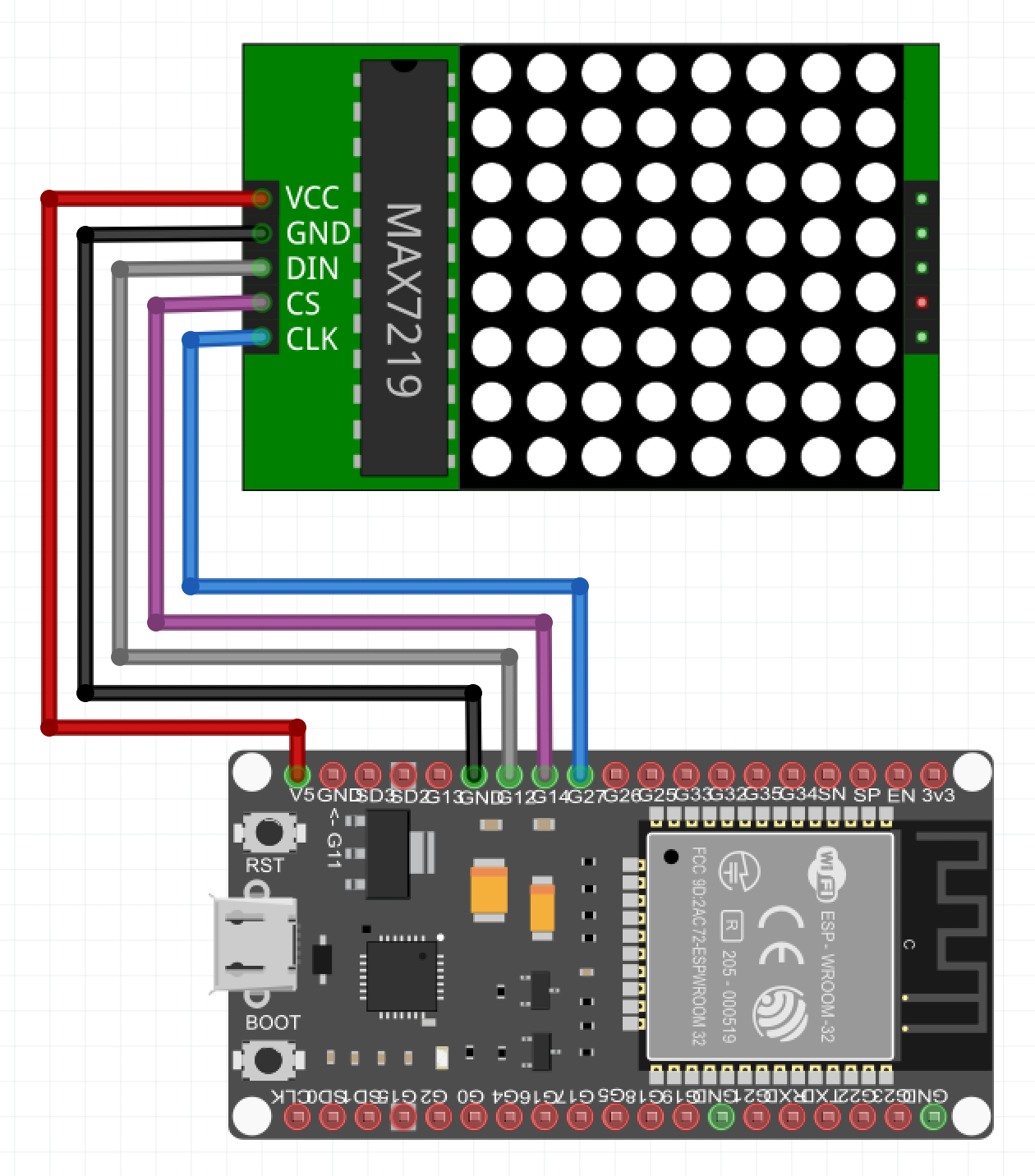
We have an ESP32 board and an 8 by 8 LED matrix driven by a MAX7219. Here is the wiring (which may vary depending on the development board you use), for an ESP32 DevKit V4 board by Espressif:

Communication with the MAX7219

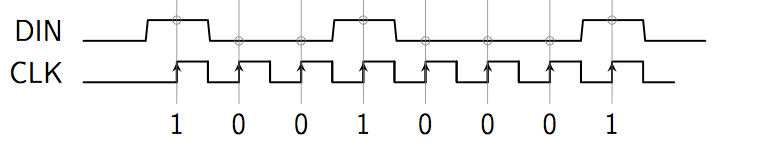
The MAX7219 communicates through a synchronous serial link according to the following chronogram:

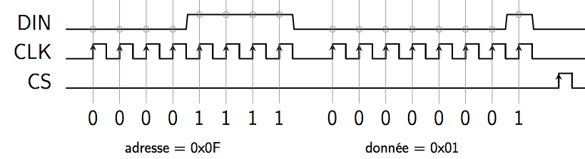
For instance, to write the data 0x01 into register 0x0F of the MAX7219, which puts it in test mode, we should have the following transmission:

This can be achieved with custom code as follows:

import machine

data = 12;    # pin connected to the serial input of the MAX7219 (DIN)
load = 14;    # pin for loading data (CS)
clk  = 27;    # pin for the clock of the serial link (CLK)

# Initialize the pins as outputs
dataPin = machine.Pin(data, machine.Pin.OUT)
loadPin = machine.Pin(load, machine.Pin.OUT)
clkPin  = machine.Pin(clk, machine.Pin.OUT)

# Set them to level 0
dataPin.off()
loadPin.off()
clkPin.off()

# Send a byte bit by bit to the MAX7219, most significant bit first
def serialShiftByte(data):
    # Set the clock to 0 in order to be able to make a rising edge later
    clkPin.off()
    # Shift the 8 bits of data
    for i in range(8):
        # left shift the data by i bits and test the most significant bit
        value = ((data << i) & 0B10000000) != 0
        dataPin.value(value)  # set the DIN pin to this value
        clkPin.on()           # create a rising edge on CLK
        clkPin.off()          # to send this bit

# Write some data in a register of the MAX7219.
def serialWrite(address, data):
    # Set CS to 0 to create a rising edge later
    loadPin.off()
    # Send the address of the register first
    serialShiftByte(address)
    # then the data
    serialShiftByte(data)
    # make a rising edge on CS to load the transmitted data into the register
    loadPin.on()
    loadPin.off()

This can also be achieved using the SPI bus interface of the ESP32:

import machine
import time

data = 12;    # pin connected to the serial input of the MAX7219 (DIN)
miso = 13;    # pin for input from the SPI bus (not used here)
load = 14;    # pin for loading data (CS)
clk  = 27;    # pin for the clock of the serial link (CLK)

# Initialize the pins as outputs
dataPin = machine.Pin(data, machine.Pin.OUT)
misoPin = machine.Pin(miso, machine.Pin.OUT)
loadPin = machine.Pin(load, machine.Pin.OUT)
clkPin  = machine.Pin(clk, machine.Pin.OUT)

# Set them to level 0
dataPin.off()
loadPin.off()
clkPin.off()

# Use software SPI bus
spi = machine.SPI(-1, sck = clkPin, mosi = dataPin, miso = misoPin)

# Send a byte bit by bit to the MAX7219, most significant bit first
def serialShiftByte(data):
    # Set the clock to 0 in order to be able to make a rising edge later
    clkPin.off()
    spi.write(data)

# Communication buffer
buffer = bytearray(2)

# Write some data in a register of the MAX7219.
def serialWrite(address, data):
    buffer[0] = address
    buffer[1] = data
    # Set CS to 0 to create a rising edge later
    loadPin.off()
    # Send the address of the register then the data
    spi.write(buffer)
    # make a rising edge on CS to load the transmitted data into the register
    loadPin.on()
    loadPin.off()

The rest of the practical session works the same as in the original version using the pyboard. You just have to replace calls to pyb.delay(ms) by calls to time.sleep_ms(ms).